Copier for a wood lathe with a manual milling cutter. Devices for the router: parallel stop, guides, compasses, table, rings Copy milling machine for wood working principle
In order to ensure the normal operation of the milling machine, it is necessary not only to properly handle the device used, but also to correctly use, in other words, devices for this tool to be able to form the workpiece in accordance with the requirements of the master (that is, cutting off the edges and other places of the material where it is needed, and not where "it happened"). So, it is precisely to give the processed material a clear planned form in the economy that "adaptations" for a manual milling cutter are used.
The complexity of making homemade devices
Often, manufacturers themselves complete their products at the production stage, but, alas, not every company will be able to please consumers with a complete set of all the necessary tools. And why do this if at any time you can make a suitable tool with your own hands in a garage environment. You can do this even without a preliminary drawing: their design is so primitive that even a novice master can cope with such work. To make a parallel stop or any other detail, it is enough to have a drawing of this device and a minimum set of tools with you. But if you want to make a homemade table for a manual router, you definitely cannot do without a drawing. It is necessary to calculate everything correctly, designate the dimensions of the table, and then proceed to work.
How to work with a manual router?
Before performing wood milling work, you need to make sure of the following:
- Is the cutter clamped in the collet.
- Whether the additional device installed on the workbench corresponds to its power and speed.
- Whether the required milling depth is set (when working with plunging devices, this indicator is measured using a special immersion limiter).
- When working with, make sure that a guide ring or bearing is installed that provides the desired trajectory of the device (in this case, the thickness of the cutter should be no more than three millimeters).

We pay attention to the supports for parts when performing work
When considering the question "how to work with a hand router" it should also be noted that the part you are processing must always have some kind of support. For example, before turning on the engine, the edge of the sole or the bearing is pressed against the guide piece or template. Only then the master turns on the machine and starts milling.
Below we will consider what are the devices for the router, and why they are special.
Parallel stop
The rip fence is one of the few devices that comes with every router. Therefore, there is simply no need for their independent development and manufacture. With regard to functions, with the help of the mentioned element, it is possible to make a reliable stop for the material being processed, thereby ensuring a rectilinear movement of the cutter relative to the base surface. The latter can act as a straight edge of a part, a guide rail or a table.

With this attachment for a hand router, you can quickly edge and mill various grooves while holding the material almost in the “dead center” position.
Guide bar
This tool has similar functions to the previous one. Like the rip fence, the rail provides exceptionally smooth straight-line movement of the device. Working with a manual wood router using a guide rail can significantly reduce the time spent on processing a particular part. In addition, with the help of the specified equipment, it is possible to install the mechanism at almost any angle relative to the edge of the table.

In some cases, the design of the tools in question provides for the presence of special elements that facilitate certain operations (for example, it can be a function of cutting holes at the same distance opposite each other).
Copy rings and templates

Hand router fixtures such as copy rings are a round plate with a raised shoulder that can slide across the surface along the template, thereby providing an accurate path for the cutter. Often this element is attached to the sole of the workbench. There are several ways to install it:
- Screwing a ring into a threaded hole.
- Installation of special antennae of the device in the holes on the sole.
With a hand router attachment such as a template, you can also achieve more accurate and efficient work. The signified

element directly on the workpiece itself, after which both parts of the device are pressed against the machine using clamps. Upon completion of the work, experts recommend checking the condition of the ring - to see if it is securely pressed against the edge of the template or not.
Another feature of the tool under consideration is the possibility of processing not the entire edge, but only its corners. At the same time, some devices for a manual milling cutter allow you to make roundings of four different radii at once. Thus, the pattern-machining process is an excellent way to cut grooves for a part.
compasses
These home-made devices for a manual milling cutter are designed to move the entire machine along a certain circle. The design of this tool includes the main part (a compass, consisting of one rod), attached with its end to the base of the router, and a secondary one - a screw with a pin inserted into the hole of the machine. The value and is set directly by the displacement of the machine relative to the design of the device. Before starting work, it is necessary to carefully fix the tool to the base and make sure that the router is in good condition and functioning properly. It is worth noting that the most effective and easy to use is the compass, which has not one, but two rods at once.

Most often, this tool is made of transparent plexiglass. A small metric scale is additionally applied to its surface. It is worth noting that some models of compasses can have a circumference up to 150 centimeters long. With the help of such a device, you can easily make a round table top for several people.
However, back to the principle of operation. By means of the angular lever with an exact scale copying on preparation is carried out. Here you have the opportunity to center the ring directly under the cutter. The angle arm, which is complemented by a special support plate, also ensures precise edge milling.
The whole structure of this fixture consists of a base plate, a set of probes and a chip protection device.
Devices for copying identical devices and parts
This characteristic refers to a set of tools, consisting of an angle lever and special copy probes, which are needed to manufacture a batch of identical parts. Most often, such equipment is used in cases where there is a need to replicate small wooden devices. But before starting work with such a router, it is necessary to prepare in advance the scale of the angle lever (scale division - 1/10 mm).

After the scale is set, you will be 100 percent sure that the thrust ring is correctly centered under the cutter, the location of which depends on the values set on the angle arm. Also, this adjusting element can be equipped with a base plate and a special mechanism that protects the surface of the device from chips. The use of such parts will significantly speed up and secure the processing of the edges of products.
Wood is one of the main materials that a person uses in everyday life for the manufacture of furniture, interior decoration, decorative architectural elements, household and garden supplies, and much more.
Wood copier.
One or two things can be done with hand tools or using woodworking equipment.
But how to process a large number of completely identical products with the least labor and time costs? In this case, copy machines will come to the rescue. One of them is a copy-milling machine for wood.
The article discusses its device and principle of operation, and also offers some advice to those wishing to make the device on their own.
Copy-milling machines (CFS) are designed for processing wood parts by copying. Varieties of the method:
- contour or 2-dimensional (2-D) milling;
- volume or 3-dimensional (3D) copying.
One method or another is used depending on the shape of the workpiece.
The main advantage of copy machines is that you can produce any number of parts with a curved contour, which are a copy of the original copy. All of them will be absolutely identical. At the same time, the machine has the flexibility to switch to another part, just change the reference.
Therefore, their scope is quite wide: from small-scale production to mass production. In addition to large enough machines for industrial use, there are also compact bench-top devices. Copy machines are used in furniture production, woodworking shops, in carpentry workshops of individual entrepreneurs.
Milling heads (milling cutter) are often used as a working unit in small machines. Its rotational speed is sufficient to ensure the required surface quality (no chips, splits, burrs).
Examples of workpieces
Below is a far from complete composition of products manufactured using FSC:
- furniture details - facades, headboards, backs, legs of armchairs and chairs;
- interior items - fireplace framing, wooden panels, frames, coasters;
- souvenir products - figurines, caskets, medallions;
- building structures - framing arched windows, filling paneled doors;
- architectural elements - bas-reliefs, decorative friezes and borders, window casings (slotted or embossed), cornice carving;
- decorative fences - railing elements, balusters, ornamental screens, fence details;
- wooden elements of the weapon - butt, fore-end;
- handles of a gardening tool, for example, an ax handle.
As you can see, the listed parts have significant differences from each other, both in size and shape. If we group them according to the most common features, it becomes obvious that processing of parts belonging to the same group requires its own design (layout) of the machine.
The principle of operation of the copier
For replication of the product, one of the copies is used, which serves as a template. The head with the cutting tool (cutter) is integrally connected to the copy probe.
In 2D milling, the probe moves along the generatrix of the copied contour, and the rotating tool repeats this movement, resulting in a copy of the template.
When milling a 3D part, the copy tip scans the 3D model and causes the cutter to move along an equidistant (similar) path. The nature of the movements of copying machines is of 2 types:
- The template and the workpiece are stationary, the cutting head moves in the longitudinal direction, removing a certain amount of material in one double stroke.
- The template and workpiece (one or more) rotate, and the cutter moves in the radial direction along the copier. As a result, it repeats the profile of the copied section. In this case, the cutting unit or part is uniformly moved along the longitudinal axis of the product.
A private type of copying and engraving work is the milling of drawings or ornaments according to a template, which is a pasted paper copy printed on a printer.
As a program for creating a drawing, you can use AVTOCAD, Compass, Word, Paint and others. In order not to break through the paper, a soft insert (wood or plastic) is inserted into the copying tip.
Choosing the layout of a homemade machine
What you need to know when starting to develop your original device.
First of all, you should determine what parts it is intended for. Next, you should select the shaping movements, the number of axes of the machine. For the processing of flat parts by the method of contour copying, 2 axes are sufficient: longitudinal and transverse movement. Details with low relief require another movement (perpendicular).
However, if the terrain is steep, then the tool axis must be additionally rotated to provide better conditions for processing. That is, it already turns out 4 axes. In some cases, 5 or more axles will be required. Introducing processing technology in your head, you should consider all possible situations. After the machine has been manufactured, adding additional movements can be problematic.
Finally, the machine must be arranged in such a way that the control forces are minimal. This means moving parts should be as light as possible. Think about which layout is better to choose: horizontal or vertical. Firstly, the convenience of work, as well as loading and unloading of workpieces, depends on it. Secondly, with a vertical layout, the chips fall directly to the floor or into the trough, and do not accumulate on the base or in the mechanisms of the machine.
The milling head should be selected as high as possible. This is an important factor affecting the quality of processing (the height of the scallops from the cutter decreases).
A few examples
Pantograph

Photo 1: machine for cutting letters.
Used for flat threads. Its design is based on a geometric figure - a parallelogram. One of the properties of this mechanism is that the nodal points describe equidistant curves during movement. Moreover, if the link is lengthened, then its end point will cover a greater distance. This property allows you to use the mechanism for scaling.
The photo shows that the total length with a copying tip at the end is about 2 times longer than the side of the parallelogram. This means that the mechanism is increasing. If you copy any figure with the tip, the cutter will reduce it by 2 times. This will reduce copier errors. Do not forget that the drawing or template is enlarged in this case.
To make a pantograph, you will need a purchased milling cutter and several dry boards. Apparently it doesn't get any cheaper.
Machine with a plane-parallel mechanism

Photo 2: contour milling
The scope is also contour milling.
Unlike a pantograph, a curvilinear trajectory is obtained by adding 2 mutually perpendicular movements. The 3rd axis is used to insert the cutter into the thickness of the part. The weight at the opposite end of the swing frame is designed to balance the system.
Pay attention to a small flaw in the design: it is better to install the load on a threaded stud in order to provide for the possibility of adjustment.
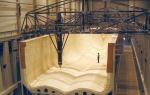
Volume Milling Machine

Photo 3: volumetric milling
In the lower part of the bed there are 2 swivel attachment points for the copier and the workpiece.
The milling head is mounted on a balanced oscillating frame, which moves along mutually perpendicular guides during operation.
Instead of linear bearings or sleeves, as in the previous device, roller carriages are used here. The advantage of the design is the open base, which facilitates the removal of chips.
duplicarver-2

Photo 4: machine for flat-relief and sculptural carving
Serial machine for flat-relief and sculptural carving. An example of simplicity: they say about such constructions - two sticks, two rolling pins. Has 5 controlled axes:
- 4 turns (side arms, swing frame, head, work tables);
- transverse movement of the head.
Longitudinal movement is obtained by adding 2 turns: levers and frame. As a power head, a German milling cutter with a power of 500 W and a spindle speed of 10 - 30 thousand revolutions per minute is used. Easily carried by one person (weight - 28 kg).
duplicarver-3

Photo 5: processing of long volumetric threads
To the previous machine, 2 more guide rolling pins (an additional linear axis) are added, and the rotary work tables are arranged vertically. As a result, it became possible to process long volumetric threads.
Below are some drawings that may be useful when making a homemade device.
Drawing 1 - pantograph device

Drawing 2 - diagram of a milling cutter mounted on a pantograph 
Drawing 3 - carriage for installing a router on a flat-copier

Video: presentation of a homemade copy machine
Do-it-yourself CNC copy machine - is it possible
All the devices discussed above have manual control, that is, despite the increase in productivity, the person remains chained to the mechanism. Such work is rather monotonous and tedious. In mass and large-scale production, copy-milling machines equipped with numerical control (CNC) are used. All work on such equipment is reduced to loading blanks and removing finished products. As an example, the photo shows a similar machine.
 The copier differs from a conventional CNC milling machine in the presence of a programming system. A traditional CNC machine works from a control program compiled by the operator in a system, for example, ARTCAM, according to a 3-D model that is developed at the design stage by a design engineer. If the product was created by a sculptor or designer, it must first be digitized, that is, a 3-D model must be created. This work is done by a software engineer.
On a CNC copy machine, the control program is compiled by the system itself. When installing a copied product, an additional CNC attachment probes the part and creates its 3-dimensional model, according to which the control program is automatically generated. Given the high cost of components, the problems with acquiring a CNC system, making your own CNC copy machine is something out of the realm of fantasy. It’s easier to make a CNC milling machine (not a copy machine), although not everyone can handle it either.
For those who are going to start their own business, making wood crafts, as well as for professional cabinetmakers, a do-it-yourself copy machine will be of great help. It can be successfully used for the purpose of decorating a country estate, outbuildings, playgrounds and other structures. Jewelry, it would seem, the work will be done effortlessly and with high quality.
Very often in our life there is a need to make a copy of some object, so the availability of copying equipment is a modern need for many enterprises. And we are not talking about copy-printing equipment, but about copy-milling machines.
They serve to create items that replicate the original sample as much as possible. The equipment makes it possible to produce parts in large quantities, providing high processing speed.
1 Features of milling
Milling is one of the methods of mechanical processing. The procedure allows for finishing, roughing and semi-finishing of various surfaces of workpieces made of wood, plastic, cast iron, metal (ferrous and non-ferrous).
Milling has a high productivity, which makes it possible to create objects of the required geometric shape.
Milling can be organized in two ways:
- passing milling, in which the directions of feed and rotation of the cutter coincide;
- up milling, in which the feed is opposite to the direction of rotation of the cutter.
Using milling cutters equipped with modern cutting materials, it is possible to carry out processing, replacing the grinding procedure.

A woodworking milling machine, including a mini modification, is used for processing the surfaces of planks, levers, covers, cases and brackets of a simple configuration, surfaces of case objects.
Allows you to apply 3D or 4D threads. One of the most popular brands domestic origin - Duplikarver.
Milling machines are found in two categories:
- specialized;
- general purpose.
The last group is continuous milling equipment, consoleless, console, longitudinal milling. The first group is copy-milling, key-milling, spline-milling, gear-milling, thread-milling. There are full and mini models.
1.1 Purpose of the machine
Copy milling woodworking machine is used for copying work on a plane and in volume, for engraving patterns, inscriptions, ornaments, shaped profiles, as well as for simple milling tasks.

Despite the simplicity of the machine, it allows you to create incredibly complex patterns. It can be mini or full size.
The equipment allows you to perform various milling work using carbide and high-speed cutting tools. Can carve. Machines are used in small and large-scale production. Can work in 3D mode with appropriate equipment, CNC. Duplicarver models are very popular.
The machine allows you to create:
- blanks and models;
- Press forms;
- various stamps;
- cams;
- forms.

The equipment can also be used for:
- drilling holes for metal hinges, handles, latches, locks;
- production of frames for mirrors;
- channels of different sizes on profiles.
The Duplicarver wood milling machine allows you to mill curved parts by copying according to a template from which the shape of the future product is copied. Through the use of templates the influence of the so-called human factor is excluded, therefore, the finished products have an identical shape. In many ways, this provides CNC.
Not only a template sample can be used in the work, subsequent products can be made according to the sample of the first one. To increase accuracy, the machine should be supplemented with a copying device called a pantograph.
It can have a different design, but it has an important function - accurate transmission along the profile of the movement of the copying head to the cutting device. Therefore, a high accuracy of the thread is achieved when it is applied.
2 Machine design
The Duplicarver milling machine uses a cutting carbide tool - a milling cutter. It reproduces the surface or contour of the copier on the product.

This machine master has a hydraulic, mechanical and pneumatic connection with a tracking system responsible for the direction of the cutter. On the one hand, it acts on the amplifying device, on the other hand, it affects the executive body.
The copier is a flat template, contour drawing, reference detail, spatial model. Copier - photocell, finger, roller or probe. Samples can be parts made of wood, plastic or metal. The copier and the workpiece to be processed are placed on a rotating table.
The executive body of the Duplicarver machine is a differential, an electromagnetic clutch, a solenoid, a screw, a spool. In amplifying devices, electro-optical, hydraulic or electromagnetic relays can be used.
The speed of movement of the tracking device determines the accuracy of the profile and the surface roughness of the product. An accuracy of 0.02 mm and a roughness of No. 6 can be achieved. The Duplicarver machine is driven by an electric motor and a power hydraulic cylinder.
The pantograph, which allows you to copy products on a set scale, has a guide pin located on the axis and moving along the copier, as well as a tool spindle and an axis of rotation.

When the finger is moved over the copier, the spindle on the workpiece describes the required geometric shape. The scale is determined by the pantograph by the proportions of the shoulders. Additionally, CNC can be used.
2.1 Types of copy milling machines
Type of drive:
- photocopiers, hydro- and electrified, with mechanical feed;
- multi- and single-spindle units with a round and rectangular table;
- universal devices with a pantograph located vertically on a swivel sleeve;
- with pantograph necessary for functioning in 2 and 3 dimensions.
There are mini and full versions. Such devices can be equipped with CNC.
You can also select more groups of devices that differ in clamping the workpiece and the level of automation:
- a desktop or manual home-made machine with a mechanical profile clamp allows you to drill holes of various shapes using a template;
- automatic machine with pneumatic profile clamping - most often used for the manufacture of aluminum structures; may have CNC;
- an automatic machine with a pneumatic profile clamp and a 3-spindle nozzle necessary for drilling triple holes (other devices do not have such an opportunity); may have CNC.
These can be mini or full size machines.
2.2 Making a machine with your own hands
Homemade copy milling machine can be done at home with your own hands. Of course, such mini equipment will not be able to work at the level of industrial designs, but it is quite capable of creating high-quality copies.

A homemade CNC woodworking copy milling machine can be made using a linkage system, an electric motor with a chuck required for a cutter.
A typical design of a do-it-yourself device is:
- Desktop;
- carrier frame;
- milling head.
Desktop copy milling machine for woodcarving with CNC do-it-yourself should be optimized for specific purposes, which must be achieved, for example, for threading. Understanding what parts to be processed, you should perform calculations of dimensions, power, and so on. Then the machine made with your own hands will allow you to implement the necessary tasks.
2.3 Operation of the copy-milling machine Duplikarver (video)
To expand the functionality of a hand-held power tool, to make its use more convenient, comfortable and safe, devices for a manual milling cutter allow. Serial models of such devices are quite expensive, but you can save on their purchase and make devices for equipping a wood router with your own hands.
Different kinds of devices can make a truly versatile tool out of a hand router.
The main task that the devices for the milling cutter solve is to ensure that the tool is located in relation to the surface to be machined in the required spatial position. Some of the most commonly used attachments for milling machines are included as standard with such equipment. The same models that have a highly specialized purpose are purchased separately or made by hand. At the same time, many devices for a wood router have such a design that making them with your own hands does not present any particular problems. For home-made devices for a manual milling cutter, drawings will not even be required - their drawings will be quite enough.
Among the devices for a wood router, which you can make yourself, there are a number of popular models. Let's consider them in more detail.
Rip fence for straight and curved cuts
It is possible to ensure the stability of the router when processing narrow surfaces without special devices. This problem is solved with the help of two boards, which are attached on both sides of the workpiece in such a way as to form one plane with the surface on which the groove is made. The milling cutter itself, when using this technological method, is positioned using a parallel stop.
To carry out a full range of woodworking with a manual milling cutter or on a milling table, you need not only conventional devices, such as cutters of various sizes, but also additional devices that will help you perform more complex work. The tool must be able to create a workpiece of the shape that is needed according to the master's idea.
Some of these devices are included with the device, but if they are not available or if you plan to make it yourself, then additional parts can be made manually. As a rule, they are quite simple to manufacture. In addition to various stops, you can also make a copier for a router with your own hands and install the structure on a frame base.
You can build a milling and copying machine yourself using a manual router. The device can be of various designs, but it has one task - to convey the movement of the working head as clearly as possible along the holder profile to the device that cuts the material.
It is not always possible to buy a ready-made machine with a copier, so it is often done independently from improvised means. It is recommended to assemble it first, it is difficult to adapt the copier to a serial device, this requires its deep alteration.
Characteristics of the works themselves
Milling cutters equipped with copiers are used for volumetric manipulations and for processing planes. They cope with works that use three-dimensional forms, engraving of various shapes, drawings, patterns, inscriptions. Simple milling functions are also within their power. Such designs are distinguished by their simplicity, but at the same time they are capable of performing surprisingly complex ornaments and shapes.
For work with such a machine, not only wood is suitable, but also cast iron, steel, non-ferrous metals, for this they use a high-speed tool made of hard alloys. On an industrial scale, on such units, but, of course, larger ones, engine blades for aircraft, ship propellers, hydraulic turbine combs, various models, metal blanks, stampings, cast and pressed parts are made.

A do-it-yourself copier is used when drilling key holes, under latches. They can make frames, grooves, channels of any size in plastic and metal profiles.
But the most interesting thing is that you can mill curvilinear parts on it, copying them according to the template. The latter allow you to make an exact copy and eliminate the human factor in such complex work. Details have an exact, perfectly identical shape.
Identical parts are made using a template, all subsequent parts can be made on the basis of the first one. For the most accurate and accurate copying, the milling cutter is equipped with a copier, such a device is also called a pantograph.
Back to index
Principle of operation and device
Briefly, the principle of operation of the copier is as follows: with the help of a probe, the contours of the original of the copied object or template are traced. The probe is connected to the working plane, at the other end of which the milling cutter is attached, so all probe movements are repeated by the milling head.
The machines have a guide system, an electric motor and a chuck for clamping a cutter or a milling cutter. A simple construction is described here.
The standard design consists of:

- working surface and supporting frame;
- milling working head;
- copy probe.
To make a do-it-yourself copier for a manual router, you will need:
- a frame made of wood or metal, if based on a lathe, then such a machine;
- boards and slats, thick plywood, wooden bars;
- fasteners (bolts, nuts, screws);
- milling cutter;
- a set of wrenches, a hacksaw for cutting the required size of wooden parts;
- metal pipe, guides;
- drills for wood and metal;
- belt drive and electric motor (if not with manual, but with automatic drive).
The working plane is set in height, the head is equipped with a drive motor and a two-stage gear mechanism, it creates two speeds of the milling shaft. This is for more complex designs.
If you have a lathe and a hand mill, you can build a very good copy machine that will work on bulk workpieces. This will require a minimum of details.
Making a copier with your own hands is not so difficult.
As the main tool take a manual milling cutter. It is installed on a base of thick plywood (12 mm), its parameters are 500/200 mm.
A hole is made on it for the sole of the router and mounting bolts. The frame and supports are also made of bars, this serves as additional stabilization and fixation of the tool. Two smaller bars are fixed to the plywood plane along the edges. The milling cutter is mounted between these two bars with pins (bolts or nails) through holes in its sole and made in plywood.
The platform with its far end slides along the pipe along the structure, that is, it is attached to a bar that walks along it. You can take a pipe made of metal 1 and ¾ inches. It is fixed between two cubic bars, it seems to hang over the machine with a carriage and a cutter. Plus, it's foldable. These bars are fastened with self-tapping screws to the frame. The pipe is set as evenly as possible along the axis of the machine, it coincides with its axis. It also has two wooden cubes with holes corresponding to it to allow it to slide. Here such a carriage is attached to them.
On the front side of the machine frame, another bar is also attached, but already horizontal, a profile template is fixed on it. It is fixed to two wooden posts vertically on both sides. The upper part of it goes exactly along the axis of the machine. If the copier is not needed, it is removed, the milling cutter leans back together with the carriage. A vertical crossbar is attached to it from below in the middle, it slides along the notches of the template, copying the relief. This is actually a copier, it is fastened with self-tapping screws, in which case it can be removed and replaced or adjusted in height. A template is attached to the bar along the facade with self-tapping screws. The platform moves by hand.
Such a machine is designed for simple volumetric parts such as chair legs, candlesticks, where there are no twisted elements.