Helicopter control principle. How does a helicopter work? General requirements include
Today, people have invented many different types of technology that can not only move along roads, but also fly. Planes, helicopters and other aircraft made it possible to explore the airspace. Helicopter engines, which were required for the normal operation of the corresponding machines, are highly powerful.
General description of the device
Currently, there are two types of such units. The first type is piston engines or the second type is air-breathing engines. In addition, a rocket engine can also act as a helicopter engine. However, it is usually not used as the main one, but is briefly included in the operation of the machine when additional power is needed, for example, during landing or takeoff.
Previously, they were often used for installation on helicopters. They had a single-shaft design, but they began to be replaced quite strongly by other types of equipment. This became especially noticeable on multi-engine helicopters. In this type of technology, the most widely used are twin-shaft turboprop helicopter engines with a so-called free turbine.
Twin-shaft units
A distinctive feature of such devices was that the turbocharger did not have a direct mechanical connection with the main rotor. The use of twin-shaft turboprop units was considered quite effective, since they made it possible to make full use of the helicopter's power structure. The thing is that in this case, the rotation speed of the main rotor of the equipment did not depend on the rotation speed of the turbocharger, this in turn made it possible to select the optimal frequency for each flight mode separately. In other words, the twin-shaft turboprop helicopter engine ensured efficient and reliable operation of the power plant.

Jet propeller drive
Helicopters also use jet propeller drive. In this case, the circumferential force will be applied directly to the propeller blades themselves, without using a heavy and complex mechanical transmission that would force the entire propeller to rotate. To create such a circumferential force, either autonomous jet engines are used, which are located on the rotor blades, or resort to the outflow of gas (compressed air). In this case, the gas will exit through special nozzle holes, which are located at the end of each blade.
As for the economical operation of a reactive drive, here it will be inferior to a mechanical one. If you choose the most economical option only among jet devices, then the best is a turbojet engine, which is located on the propeller blades. However, constructively creating such a device turned out to be too difficult, which is why such devices did not receive widespread practical use. Because of this, helicopter engine factories did not begin mass production.

The first models of turboshaft devices
The first turboshaft engines were created back in the 60-70s. It should be mentioned that at that time such equipment fully met all the needs of not only civil aviation, but also military aviation. Such units were able to provide parity, and in some cases, superiority over the inventions of competitors. The most mass production of turboshaft helicopter engines was achieved through the assembly of the TV3-117 model. It is worth noting that this device had several different modifications.
In addition to it, the D-136 model also received good distribution. Before the release of these two models, the D-25V and TV2-117 were produced, but at that time they could no longer compete with the new engines, and therefore their production was stopped. However, it is fair to say that quite a lot of them were produced, and they are still installed on those types of air transport that were released quite a long time ago.

Equipment gradation
In the mid-80s, a need arose to unify the design of a helicopter engine. To solve the problem, it was decided to bring all turboshaft and turboprop engines available at that time to a common size range. This proposal was accepted at the government level, and therefore a division into 4 categories arose.
The first category is devices with a capacity of 400 hp. s., second - 800 l. s., third - 1600 l. With. and the fourth - 3200 l. With. In addition, the creation of two more models of helicopter gas turbine engine was authorized. Their power was 250 hp. With. (0 category) and 6000 l. With. (category 5). In addition, it was assumed that each category of these devices would be capable of generating power by 15-25%.

Further development
In order to fully ensure the development and construction of new models, CIAM conducted quite extensive research work. This made it possible to obtain a scientific and technical basis (NTR), according to which the development of this area will proceed.
This NTZ indicated that the operating principle of helicopter engines of future generations should be based on the simple principle of the Brayton thermodynamic cycle. In this case, the development and construction of new units will be promising. As for the design of the new models, they should have a single-shaft gas generator, and a power turbine with a forward output of the power shaft through this gas generator. In addition, the design must also include a built-in gearbox.
In accordance with all the requirements of the scientific and technical background, work began at the Omsk Design Bureau on the production of such a helicopter engine model as the TV GDT TV-0-100, the power of this device was supposed to be 720 hp. s., and it was decided to use it on a machine such as the Ka-126. However, in the 90s, all work was stopped, despite the fact that at that time the device was quite advanced, and also had the ability to boost power to indicators such as 800-850 hp. With.
Production at OJSC Rybinsk Motors
At the same time, Rybinsk Motors OJSC was fine-tuning an engine model such as the TV GDT RD-600V. The power of the device was 1300 liters. s., and they planned to use it for such a type of helicopter as the Ka-60. The gas generator for such a unit was made according to a fairly compact design, which included a four-stage centrifugal compressor. It had 3 axial stages and 1 centrifugal stage. The rotation speed provided by such a unit reached 6000 rpm. An excellent addition was that such an engine was additionally equipped with protection from dust and dirt, as well as from the ingress of other foreign objects. This type of engine has undergone many different tests, and its final certification was completed in 2001.
Further, it is worth noting that in parallel with the refinement of this engine, specialists worked on the creation of the TVD-1500B turboprop engine, which was planned to be used on An-38 helicopters. The power of this model is only 100 hp. With. higher and thus amounted to 1400 l. With. As for the gas generator, its layout and equipment were the same as on the RD-600V model. During their development, creation and configuration, it was planned that they would form the basis for a family of engines such as turboshafts and turboprops.
Motorcycle with helicopter engine
Today, the production of various types of equipment has advanced quite widely. This is true for almost all industries, including motorcycle manufacturing. Each manufacturer always tried to make its new model more unique and original than its competitors. Because of this desire, Marine Turbine Technologies recently released the first motorcycle that was powered by a helicopter engine. Naturally, this change greatly affected both the structural part of the machine and its technical characteristics.

Equipment parameters
Naturally, the characteristics of a motorcycle that has a helicopter engine at its disposal also has unique technical parameters. In addition to the fact that such an innovation made it possible to accelerate the motorcycle to an almost unimaginable 400 km/h, there are other properties that are also worth paying attention to.
Firstly, the fuel tank volume of this model is 34 liters. Secondly, the weight of the equipment has increased quite significantly and amounts to 208.7 kg. The power of this motorcycle is 320 horsepower. The maximum possible speed that could be achieved on such a device is 420 km/h, and the size of its rims is 17 inches. The last thing worth mentioning is that the operation of the helicopter engine greatly affected the acceleration process, which is why the equipment reaches its limit in a matter of seconds.

The first such creation that Marine Turbine Technologies showed to the world was called Y2K. Here we can add that the exact acceleration time to 100 km/h takes only one and a half seconds.
To summarize all of the above, we can say that the industry for creating helicopter engines has come a long way, and the current development of technology has made it possible to use products even in equipment such as motorcycles.
These days, a helicopter is the most versatile aircraft. In many countries it is called " helicopter", which was formed from two Greek words, translated meaning "spiral" and "wing". A helicopter, hovering in one place for a long time, can then fly in any direction without even making a turn. And he also does not need special runways, because he is able to take off vertically without a “run” and make a vertical landing without a “run”. Thanks to this, helicopters are widely used for transport to hard-to-reach places, for firefighting, sanitary and rescue work.
The main difference between a helicopter and an airplane is that it takes off without acceleration and rises up in a vertical position. The helicopter does not have wings, but instead has a large propeller located on the roof and a small propeller on the tail. The main advantage of a helicopter is maneuverability. It can hover in the air for a long time and, in addition, fly in reverse. To land, the helicopter does not require an airfield: it can land on any flat area, even high in the mountains.
At the beginning of the twentieth century, the Frenchman P. Cornu was the first in the world to fly a helicopter. He managed to fly to a height of 150 centimeters, that is, he hung in his invention somewhere at the chest level of an adult man. Then this flight lasted only 20 seconds. Paul Cornu decided that the height was too high, and he was taking a lot of risks, so subsequently he soared upward only with a safety net - on a leash.
The main design element that makes a helicopter take off and then soar through the skies is its large propeller. It constantly scoops up air with its blades, which is why the helicopter flies. At the same time, the tail rotor prevents the body of this flying bird from turning in the opposite direction of rotation of the main rotor. This helicopter design was invented in the 1940s by a Russian engineer.
When the main rotor of a helicopter rotates, a reaction force arises, spinning it in the opposite direction. Depending on the method of balancing this force, there are single-rotor and twin-rotor helicopters. In single-rotor helicopters, the reaction force is eliminated by an auxiliary tail rotor, and in twin-rotor helicopters, due to the fact that the rotors rotate in opposite directions.

Types of helicopters.
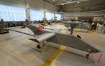
The main purpose of attack helicopters is to defeat enemy ground targets. These are the best military helicopters, which is why such machines are also called attack helicopters. Their weapons consist of guided anti-tank and aircraft missiles, heavy machine guns and small-caliber guns.

An attack helicopter can destroy a huge amount of enemy equipment and manpower in one battle. The Eurocopter Tiger attack helicopter is in service with the armies of France, Spain, Germany and Australia.
The Russian Ka-50 helicopter is considered one of the most maneuverable attack helicopters in the world. It is widely known in the world under the nickname Black Shark. This helicopter is equipped with two large propellers, and its tail is like an airplane. The Black Shark helicopter performs the most complex aerobatics and is capable of hovering in the air for up to 12 hours. Thanks to modern automation, the Ka-50 is controlled by only one pilot.

In 1983, the AN-64 Apache attack helicopter was created in the US state of Arizona. Its armament included an automatic rapid-fire cannon and 16 guided anti-tank missiles. The Apache helicopter can reach speeds of up to three hundred kilometers per hour and fly at an altitude of 6 kilometers. This helicopter maneuvers perfectly both in pitch darkness and during the worst weather conditions. The Apache helicopter is still the main helicopter used by the US Army today.

A transport helicopter can be used to transport both passengers and cargo. Other types of helicopters include a special rescue helicopter and a light two-seat research helicopter.

.
Main rotor of a helicopter: one or more (usually two) main rotors are used for flight. Its blades (up to 8 pieces) act like airplane wings and, when rotating, create the necessary lifting force. At first, the blades were made of metal, and since the late fifties of the last century they have been made of fiberglass.
The auxiliary rotor serves to eliminate the reaction force that spins the helicopter in the opposite direction when the main rotor rotates. Sometimes, instead of a propeller, a jet nozzle can be installed on the tail boom. Helicopter engine A drives the main and auxiliary screws to rotate. This is usually a piston or jet engine.

Pilot in the cockpit V there is a control rudder (steering wheel), which is turned by the pilot to fly in the direction he needs. The rudder changes the inclination of the propeller blades; during flight, one part of the circle that the propeller describes will be lowered lower than the other, and the helicopter will fly in that direction.
The fuselage includes the cockpit, passenger or cargo compartment, and engine compartment. Chassis - since a helicopter does not need to “jog” for takeoff and landing, very often the wheeled chassis is replaced with more convenient skis.
20.06.2015
Principle of airplane and helicopter flight
Any body moving in the air continuously experiences resistance to its movement from the latter. Therefore, in order to move the body, you need to overcome resistance and apply some force. The force of air resistance encountered by a body moving in it is directly proportional to the density of the air, the area of the body, the square of the speed of movement and depends on the shape of the body, its smoothness and position in the air flow.
Based on this basic law of aerodynamics, it can be established that if the same force is given to bodies of different shapes and sizes placed in different environments, then their speed of movement will be different.
If you place bodies of various shapes in the air flow - a plate, a body with angular shapes and a drop-shaped body, then it turns out that the greater the pressure difference in front and behind them, the larger the vortex area, the lower the speed of movement of bodies in the air and the greater the resistance force. This force, directed directly against the motion of the bodies, is called the drag force, or drag.
When flowing around a body with angular shapes, the flow slows down less than when flowing around a plate; therefore, both the region of low pressure and the drag will be smaller (Fig. 1).
If a drop-shaped body with a more perfect aerodynamic shape is placed in the air flow, then the pressure in front and behind this body will be insignificant, since the streams of air flow tightly around it and almost do not form turbulence. In the presence of such bodies, the least force will be required to overcome drag. From the above, it becomes clear that in aviation, streamlined body shapes that create the lowest possible resistance and do not cause turbulence are of decisive importance. To such bodies before
These include teardrop-shaped and wing-shaped bodies. The wings of an airplane are its main parts. They create lift and make flight possible.
Let us consider in general terms the causes of lift (Fig. 2). Let the wing move in the air at a certain angle of attack. Air particles hitting a flying wing will bend around both the upper, convex, and lower, flat or slightly concave surface of the wing. At the same time, the streams flowing around the wing from above have to travel a longer distance than the streams flowing around the wing from below. This means that the upper streams will move at a higher speed than the lower ones.

From Bernoulli's law it follows that the higher the flow speed, the lower the pressure in it. Therefore, less pressure is created above the wing than below the wing. As a result of the pressure difference, the wing, on the one hand, seems to be sucked upward due to the reduced pressure, and on the other hand, it is also propped up due to the increased pressure. As a result, a lifting force arises, acting from the bottom up and directed perpendicular to the air flow. The flight of airplanes and helicopters as heavier-than-air vehicles is based on this property of the wing.
An airplane only gains lift if it is moving at sufficient speed. In order for an airplane to lift off the ground, the lift from its wing must be greater than the weight of the airplane.
In order for an airplane to move in the air at a certain speed, it must constantly overcome air resistance, and during the takeoff run, also the friction of the wheels on the ground. The force that overcomes air resistance and imparts forward speed to the aircraft is the thrust of the propeller rotated by the motor.
Airplane structure
The main parts of the aircraft include wings, a body, stability and control organs, organs for movement and landing, and a propeller-engine group (Fig. 3).
Wings are one of the most important parts of an aircraft. The flight performance of the aircraft depends on the shape in plan and cross section, as well as on the size of the wings.
A monoplane type aircraft has one wing, while a biplane type aircraft has two wings. The upper and lower wings are connected to each other by struts. Ailerons are hinged to the upper and lower wings. In plan, an aircraft wing with aileron most often has a rectangular shape with elliptical rounding of the ends.

The aircraft body (fuselage) is the main part of the structure to which the center section, wings, engine unit, landing gear and tail are connected. In addition, it serves to accommodate the aircraft's payload (passengers, cargo, etc.).
The aircraft's stability and control organs consist of ailerons and the tail.
Ailerons are part of the wing and are small movable wings located at the ends of the aircraft's wings. Ailerons serve to maintain lateral stability of the aircraft and to tilt it when turning around its longitudinal axis.
The tail of an aircraft consists of horizontal and vertical tails. With their help, the aircraft maintains longitudinal stability in the air, rises up, descends and changes direction of flight.
The horizontal tail consists of a stabilizer - a fixed part that provides the aircraft with longitudinal stability in flight (in the vertical direction), and a moving part - elevators. They are the controls of the aircraft in the vertical plane and serve to transfer it to rise or fall.
The vertical tail consists of a fin, fixedly connected to the rear part of the fuselage and serving to impart stability to the aircraft in flight (in the horizontal direction), and a moving part - the rudder, which is an organ of directional stability and controllability. With its help, you can change the direction of flight of the aircraft to the right and left, i.e. in the horizontal plane.
The organs for movement and landing are the landing gear with a tail or front wheel. An aircraft's landing gear is a takeoff and landing device necessary for the takeoff run, softening the impact of landing, and improving controllability when taxiing on the ground. In winter conditions, a tail ski (ski) is installed to protect against burying in the snow.
The aircraft lands on three points, for example on two front wheels and one tail.
The aircraft is controlled using elevators, rudder and ailerons. The main requirement for an aircraft in flight is stability and controllability relative to three axes (Fig. 4) passing through the center of gravity of the aircraft - the longitudinal axis XX1, the transverse axis YU1 and the vertical axis ZZ1, perpendicular to these axes. Aircraft controllability around the longitudinal axis is achieved by ailerons, the transverse axis by elevators, and the vertical axis by rudder. A steering wheel and foot pedals are used to control the aircraft. The helm connects to the elevators and ailerons, and the foot pedals connect to the rudder and tail wheel. When the steering wheel is deflected to the left, the ailerons of the left wings rise and the ailerons of the right wings lower; in this case, the plane gets a left bank. When you take the helm, the elevators rise and the plane goes up. When you move the helm away from you, the plane will descend.

The rudder is controlled by pressing the pedal with your foot. For example, pressing with your right foot will turn the rudder to the right and the plane will turn to the right.
The propeller-engine group consists of a motor, a propeller, a motor frame, a gas and oil supply system and motor control. An airplane propeller has several blades of right rotation (clockwise).
Applicable aircraft and requirements for them
Aircraft used for aerial photography of forests and forestry are subject to different requirements.
In forestry, for protecting forests from fires, extinguishing them, aerial taxation of forests, aerochemical control of harmful insects and other work, the YAK-12 and AN-2 aircraft are most widely used. The PO-2 aircraft is out of production.
The Yak-12 aircraft is a monoplane, with a closed but well-glazed cabin, which seats four people, including the pilot. Convenient for aerovisual observations, has good visibility and low flight speed - 90-150 km/h. Large- and medium-scale aerial photography from it is possible only for forestry purposes, subject to low requirements regarding strict compliance with the flight altitude and inclination angle of the aerial photographs.
The AN-2 aircraft is widely used for aviation protection of forests from fires, extinguishing them, aerochemical control of harmful insects, transport of people and cargo, as well as for aerial photography. Its cabin can easily accommodate two aerial cameras, special equipment for them, including a radio altimeter, a statoscope, and other instruments, and a crew of up to six people. This allows simultaneous aerial observations of forest areas. With good stability in the air and a cruising speed of 130-210 km/h, it is suitable for medium and large-scale aerial photography. Its visibility for aerovisual observations is worse than that of the Yak-12.
The LI-2 and IL-12 aircraft are equipped with the most advanced flight and aeronautical instruments, have a high payload and flight speed (230-400 km/h), and a practical flight altitude of up to 5000 m, which allows them to be used for small- and medium-scale aerial photography.
Specific requirements for aerial photography aircraft include:
1. The need to have sufficient cabin dimensions to accommodate aerial cameras and all equipment for them (radio altimeters, statoscopes and control instruments) and to create the ability to control them in flight and troubleshoot minor faults.
2. Possibility of good visibility for the aerial surveyor forward, to the sides and down.
3. The ability to quickly gain altitude up to 6000 m, have a cruising speed of up to 350 km/h, and have a fuel reserve for 6-8 hours of flight.
4. In a given horizontal flight mode, the aircraft must have good longitudinal, lateral and directional stability in order to meet the requirements for the geometric quality of the photographic image of the terrain.
For aviation services in forestry, it is necessary to have both light aircraft, convenient for aerovisual observations, with a large speed range - from 80 to 200 km/h, allowing flights at low altitude, and heavy aircraft with a carrying capacity of several tons, capable of transporting cargo. , workers, parachutists, various mechanisms and at the same time suitable for landing and takeoff from small areas.
Helicopter device
A helicopter is a heavier-than-air aircraft. Its foreign name is “helicopter”, which comes from the Greek words hélicos (screw) and pteron (wing), i.e. rotorcraft. The Russian name “helicopter” indicates the main feature of this aircraft - “vertical flight”.
The helicopter is capable of taking off vertically, straight from a standstill, and landing vertically, without running. In the air, it can move in any direction and can hang motionless both above the forest canopy and at an altitude of several hundred meters. A helicopter can land in a clearing in the middle of a forest, in a dry treeless swamp, etc. Takeoff and landing speeds, takeoff and run lengths are zero, so the helicopter does not need special airfields; it is a representative of non-airfield aviation. The helicopter has a wide speed range - from 0 to 150-200 km/h. Thanks to these properties, it is an indispensable means of communication, transport, and for performing various tasks when exploring inaccessible places in the uninhabited conditions of the North and Siberia.
The main parts of a helicopter include; main rotor, body, engine, transmission, helicopter control system, steering (tail) rotor and landing gear (Fig. 5).
The main rotor of a helicopter plays the role of a wing. It is driven by an engine and serves to create lift and thrust. In addition, the main rotor is the control element of the helicopter. Helicopters use rotors with three to four long and narrow (15-20 liters or more in diameter) blades. The main rotor blades can rotate about their axis in an axial hinge.
The helicopter's vertical movement is controlled by changing the rotor speed or the angle of the blades. As the rotor speed or blade angle increases, the lift force increases and the helicopter rises. If the propeller speed drops or the installation angle decreases, the lift decreases and the helicopter decreases. When the lifting force is completely balanced by the flight weight of the helicopter, it “hangs” in the air, without descending or rising. As soon as the lift force exceeds the weight of the helicopter, it rises. While rotating, the main rotor tends to turn the helicopter in the direction opposite to the rotation of the rotor, i.e., a reactive torque is created. To balance it, a tail rotor is used, which, when rotated, creates thrust and balances torsion.
The body of a helicopter performs the same functions as an airplane. It connects all the parts into one whole. It houses the engine, control system, special equipment, transmission mechanism, cabin for the pilot and cargo.
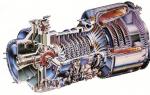
Power plant and transmission. Modern helicopters use conventional air-cooled internal combustion piston engines, aviation gas turbines and turbojet engines.
In order to transfer engine power to the main and tail rotors, a special mechanism called a transmission is used.
The control of, for example, a single-rotor helicopter consists of three systems; main rotor control, tail rotor control and engine throttle control.
The main rotor is controlled by a conventional aircraft-type control stick using an automatic swashplate and a “step-throttle” lever. The tail rotor is controlled by conventional foot pedals. The engine is controlled by the same “step-throttle” lever that controls the main rotor.
The “step-throttle” lever is so called because when it moves, the pitch of the propeller and the power (throttle) of the engine simultaneously change. For example, when the “step-throttle” lever moves downwards, the installation angles or the pitch of the main rotor blade will decrease, and the engine power will also decrease. Consequently, the helicopter will begin to descend.
The tail rotor is installed only on single-rotor helicopters. It balances the reactive torque of the main rotor and provides directional control, i.e., it is used to perform a turn.
The landing gear serves to absorb possible shocks and shocks during landing and as a support when parking. The chassis can be wheeled, float and skid.
Light helicopters usually have three wheels, while heavy ones have four.
Helicopter classification
Helicopters differ in the number of rotors, their location, and the method of driving rotation. In accordance with these characteristics, helicopters can be single-rotor with a tail rotor, with two rotors located coaxially, with two longitudinally located rotors, with two transversely located rotors, with a jet drive of the main rotor, etc. (Fig. 6).
The most common are single-rotor helicopters with a tail rotor designed by M.L, Mil (MI-1, MI-4, MI-6, V-2, V-8, etc.). They are simple in design and operation. Their disadvantages are a long tail (large dimensions) and a significant loss of power (up to 10%) due to the operation of the tail rotor.

Helicopters of coaxial design have both rotors on the same axis, one below the other. The shaft of the upper screw passes inside the hollow shaft of the lower screw. Due to the rotation of the rotors in opposite directions, the reactive torque is suppressed. These helicopters are small in size, light in weight, have good controllability and maneuverability,
The disadvantages of coaxial helicopters include the loss of power by the lower rotor, which operates in a stream of air thrown by the upper rotor, and the difficulty of calculations during design.
According to this scheme, light helicopters N.I. are being created. Kamov: single-seat KA-10, double-seat KA-15 and four-seat KA-18.
Helicopters with two longitudinally located rotors have one rotor located above the nose of the fuselage, and the other above the tail. The screws rotate in opposite directions to mutually cancel out the reactive torque. Their disadvantage is that the rear propeller operates in an air environment previously disturbed by the front propeller, and this reduces its efficiency.
The propellers of helicopters with two transverse rotors are mounted on special beams on the sides of the fuselage. Rotating in opposite directions, they create good lateral stability.
The helicopter engine is used to rotate the main rotor. If a helicopter has several main rotors, then they can be driven by one common engine or each by a separate engine, but so that the rotation of the rotors is strictly synchronized.
The purpose of an engine on a helicopter differs from the purpose of an engine on an airplane, gyroplane, or airship, since in the first case it rotates the main rotor, through which it creates both thrust and lift, in other cases it rotates the tractor rotor, creating only thrust. the reaction force of a gas jet (on a jet aircraft), which also provides only thrust.
If a helicopter is equipped with a piston engine, then its design must take into account a number of features inherent to the helicopter.
A helicopter can fly in the absence of forward speed, that is, hang motionless relative to the air. In this case, there is no airflow and cooling of the engine, water radiator and oil cooler, as a result of which the engine may overheat and fail. Therefore, on a helicopter it is more expedient to use an air-cooled engine rather than a water-cooled one, since the latter does not need a heavy and bulky liquid cooling system, which would require very large cooling surfaces on a helicopter.
An air-cooled engine, usually installed on a helicopter in a tunnel, must have a drive for a forced-air fan, which provides cooling to the engine during hovering and level flight, when the speed is relatively low.
An oil cooler is installed in the same tunnel. The temperature of the engine and oil can be adjusted by changing the size of the inlet or outlet openings of the tunnel using movable flaps controlled from the cockpit manually or automatically.
An aircraft piston engine typically has a rated speed of about 2000 rpm. It is clear that the full number of engine revolutions cannot be transferred to the propeller, since in this case the tip speeds of the blades will be so high that they will cause a high-speed stall. For these reasons, the M number at the ends of the blades should be no more than 0.7-0.8. In addition, with high centrifugal forces, the main rotor would be of heavy construction.
Let's calculate the maximum permissible revolutions of a rotor with a diameter of 12 m, at which the number M of the ends of the blades does not exceed 0.7 for a flight altitude of 5000 m at a flight speed of 180 km/h,

So, a helicopter engine must have a gearbox with a high degree of reduction.
On an airplane, the engine is always rigidly connected to the propeller. A durable, small-diameter all-metal propeller easily withstands the jerks that accompany the start of a piston engine, when it suddenly picks up several hundred revolutions. A helicopter rotor, having a large diameter, masses far spaced from the axis of rotation, and therefore a large moment of inertia, is not designed for sudden variable loads in the plane of rotation; When starting, damage to the blades may occur due to starting jerks.
Therefore, it is necessary that at the time of launch the helicopter’s main rotor is disconnected from the engine, i.e., the engine must be started idle, without load. This is usually done by introducing friction and cam clutches into the engine design.
Before starting the engine, the clutches must be turned off, and the rotation of the engine shaft is not transmitted to the main rotor.
However, without load, the engine can develop very high speeds (spin), which will cause its destruction. Therefore, when starting, before the clutches are engaged, you cannot fully open the engine carburetor throttle and exceed the set speed.

When the engine is already running, it is necessary to connect it to the main rotor using a friction clutch.
A hydraulic coupling consisting of several metal discs coated with a material with a high coefficient of friction can serve as a friction clutch. Some of the disks are connected to the engine gearbox shaft, and the intermediate disks are connected to the main shaft drive to the main rotor. As long as the disks are not compressed, they rotate freely relative to each other. The compression of the discs is carried out by a piston. Supplying high pressure oil under the piston causes the piston to move and gradually compress the discs. In this case, the torque from the engine is transmitted to the propeller gradually, smoothly unwinding the propeller.
The revolution counters installed in the cockpit show the engine and propeller revolutions. When the engine and propeller speeds are equal, this means that the hydraulic clutch discs are pressed tightly against each other and the clutch can be considered to be connected as a rigid clutch. At this moment, the dog clutch can be engaged smoothly (without jerking).
Finally, to ensure the possibility of self-rotation, the main rotor must be automatically disconnected from the engine. As long as the engine is running and turning the propeller, the dog clutch is engaged. If the engine fails, its speed quickly decreases, but the main rotor continues to rotate for some time by inertia at the same number of revolutions; at this moment the dog clutch disengages.
The main rotor, disconnected from the engine, can then continue to rotate in a self-rotating mode.
Flight in self-rotation mode for training purposes is carried out with the engine turned off or with the engine running; in the latter case, its speed is reduced so much that the propeller (taking into account the reduction) makes a greater number of revolutions than the engine crankshaft.
After the helicopter lands, the engine speed is first reduced, the clutch is disengaged, and then the engine stops. When parking a helicopter, the propeller must always be braked, otherwise it may begin to rotate due to gusts of wind.

Helicopter engine power is spent on overcoming the rotor rotation resistance, on tail rotor rotation (6-8%), on fan rotation (4-6%) and on overcoming transmission losses (5-7%).
Thus, the main rotor does not use all the engine power, but only part of it. The propeller's use of engine power is accounted for by a coefficient that shows how much of the engine power the rotor uses. The higher this coefficient, the more advanced the helicopter design. Typically = 0.8, i.e. the propeller uses 80% of the engine power:
The power of a piston engine depends on the weight charge of the air drawn into the cylinders, or on the density of the surrounding air. Due to the fact that the density of the surrounding air decreases with increasing altitude, the engine power also constantly decreases. Such an engine is called a low-altitude engine. With an increase to a height of 5000-6000 m, the power of such an engine is reduced by approximately half.
In order for the engine power not only to decrease, but even to increase up to a certain altitude, a supercharger is installed on the air suction line into the engine, increasing the density of the intake air. Due to the supercharger, the engine power increases up to a certain altitude, called the design altitude, and then decreases in the same way as in a low-altitude engine.
The supercharger is driven into rotation from the engine crankshaft. If there are two speeds in the transmission from the crankshaft to the supercharger, and when the second speed is turned on, the speed of the supercharger increases, then with an increase in height it is possible to provide an increase in power twice. Such an engine already has two design heights.
Helicopters, as a rule, have engines with superchargers.