Measurement of roll and pitch angles, measurement of slip. See what “Roll” is in other dictionaries Preventing ship roll
On its side) - the deviation of the plane of symmetry of the aircraft from the local vertical to the earth's surface. It is characterized by the K angle and K speed. Roll angle(γ) - angle between the transverse axis OZ and the normal axis OZ(m) ( cm. coordinate system) shifted to a position where the yaw angle is zero. Angle K is considered positive when the OZg axis is aligned with the OZ axis by rotating clockwise around the OX axis when viewed along this axis. When determining the orientation of the velocity coordinate system (SV) relative to the normal one, it is used speed roll angle(γ)a, defined similarly to the angle (γ), but instead of the OZ axis, the lateral OZa axis is considered. When describing the movement of rockets they use aerodynamic bank angle(φ)n, defined as the angle between the OY axis and the OYn CK axis associated with the spatial angle of attack.
The roll of an aircraft is also the name given to the movement in which the bank angle changes; characterized roll rate(ω)x - projection of the angular velocity of the aircraft onto its longitudinal axis. The speed of rotation is considered positive when the aircraft rotates clockwise around the OX axis. When analyzing K. they often use dimensionless speed K. -(ω)x, related to the speed of K. by the relation
(ω) = (ω)xl/2V,
where l is the aircraft, V is the flight speed.
The dimensionless speed of K is also called helix angle described by the tip of the wing.
Aircraft maneuvers are used, for example, during turns, when performing aerobatic maneuvers, and during landing approaches to counteract the displacement of the aircraft’s trajectory relative to the axis of the runway. Control of the gearbox is carried out by lateral control bodies ( cm. Controls). Spontaneous flight of an aircraft is called a fall. Cm. also Lateral movement.
Aviation: Encyclopedia. - M.: Great Russian Encyclopedia. Editor-in-Chief G.P. Svishchev. 1994 .
Synonyms:
See what “Kren” is in other dictionaries:
bank- roll, and... Russian spelling dictionary
bank- roll / ... Morphemic-spelling dictionary
bank- a, m. carène f., English. carren, goal krengen 1. mor. The underwater or lower part or surface of the Vessel at the waterline. Marine science. 386. // Sl. 18 10 249. 2. Tilt of the vessel to one side. Sl. 18. The roll when testing the slope with guns decreased somewhat. CSF 2 30 ... Historical Dictionary of Gallicisms of the Russian Language
Models of the aircraft Kren (from the French carène keel, the underwater part of the ship or from the English kren gen ... Wikipedia
- (English careen, from Latin carina - underwater part of the ship). The condition of a tilted ship, the ship's deviation due to the wind or due to the transfer of weights to one side, for underwater repairs. Dictionary of foreign words included in the Russian language.... ... Dictionary of foreign words of the Russian language
Cm … Synonym dictionary
Kren, roll, husband. (specialist.). 1. Tilt of a ship or aircraft on its side. The steamer is moving with a strong list. Give a roll (tilt). 2. transfer Bias, change in political orientation (newspaper). The Austrian socialists have made a big shift to the right... Ushakov's Explanatory Dictionary
A; m. 1. Lateral tilt of a ship or airplane. Give the ship's K. K. increases. 2. Change of direction, turn in political, social, etc. activities. K. left, right. Take it to the side. * * * ROLL ROLL (from Dutch krengen - to lay the ship on ... ... encyclopedic Dictionary
KREN, ah, husband. 1. Tilt to one side (of a ship, aircraft, vehicle). Give to. Put the plane in room 2. transfer. Unilateral change in direction. Ozhegov's explanatory dictionary. S.I. Ozhegov, N.Yu. Shvedova. 1949 1992 … Ozhegov's Explanatory Dictionary
ROLL, see heel. Dahl's Explanatory Dictionary. IN AND. Dahl. 1863 1866 … Dahl's Explanatory Dictionary
- (List, heel, heeling) 1. Transverse inclination of the vessel. 2. The tilt of the aircraft about the longitudinal axis. 3. The underwater part of the ship along the waterline (old). Samoilov K.I. Marine dictionary. M.L.: State Naval Publishing House of the NKVMF of the USSR ... Marine Dictionary
Books
- My gentle shore, Krenev P.. The book of the famous modern prose writer includes works telling about life in the Russian North about modern Pomors inhabiting the shores of the White Sea. This is a reliable, true story...
Let us consider the movement of a cargo weighing ρ on a ship in the transverse-horizontal direction to the starboard side at a distance l y. This movement of the load will cause a roll and displacement of the center of gravity. of the vessel in a direction parallel to the line of movement of the cargo ρ. The initial lateral stability will not change in this case, since applicates Ts.V. and C.T., as well as the metacentric radius and metacentric height will not receive any increment. The vessel's gravity applied in the new C.T. and the supporting force applied in the new C.E. will act along the same vertical, perpendicular to the new waterline B 1 L 1.
Rice. 1
At the same time, the ship takes a new equilibrium position, tilting at a roll angle. It follows from the figure that the moment that appears as a result of the movement of the load across the vessel can be determined from the expression:
Mkr=P lу cos θ
The righting moment can be determined by the metacentric stability formula. The vessel is in equilibrium under the influence of a modified system of forces, therefore the moments Mcr and Mθ are also equal:
Р·lu·cos θ=D’·h·sin θ
Solving this equation for θ, we obtain a formula for determining the roll angle during transverse movement of the load:
tgΘ=Р·luD'·h
Since the roll angle is small, the last expression can be written as:
Θ=Р·luD'·h
The above formula is used in cases where the roll angles do not exceed 10-15 degrees.
Change in ship stability when moving cargo vertically
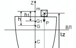
Let us assume that on a ship sitting on an even keel and in equilibrium, a load weighing P is moved vertically to a distance l z. Since the vessel's displacement does not change due to the movement of the cargo, the first equilibrium condition will be met (the vessel will maintain its draft). According to the well-known theorem of theoretical mechanics, C.T. the vessel will move to point G 1, located on the same vertical with the previous position of the center of gravity. vessel G. The vertical itself will pass, as before, through the Ts.V. vessel C. Thus, the second condition of equilibrium will be met, therefore, with a vertical movement of the load, the ship will not change its equilibrium position (no roll or trim will appear).
 Rice. 2
Let us now consider the change in the initial lateral stability. Due to the fact that the shape of the ship's hull submerged in water and the shape of the waterline area have not changed, the position of the Ts.V. and the transverse metacenter (t. m) remains unchanged when the load moves vertically. Only the C.T. moves. vessel from point G to point G 1. The segment GG 1 can be found using the expression:
If before moving the load the transverse metacentric height was h, then after moving it it will change by the value GG 1. In our case, the change in the transverse metacentric height Δh = GG 1 has a negative sign, since the movement of the C.T. the vessel towards the transverse metacenter, the position of which, as we have established, remains unchanged, reduces the metacentric height. Therefore, the new value of the transverse metacentric height will be:
h1=h-Р lzD (1)
Obviously, in the case of moving the load down, a plus sign (+) must be placed in front of the second term on the right side of the equation of the new metacentric height h1.
From expression (1) it follows that the decrease in the stability of the vessel is proportional to the product of the mass of the cargo and its movement in height. In addition, all other things being equal, the change in lateral stability will be relatively less for a ship with a large displacement than for a ship with a small D. Therefore, on large ships, the movement of relatively large loads is safer than on small ships.
It may turn out that the value of GG 1 moves up C.T. the vessel will be greater than the value of h itself. Then the initial lateral stability will become negative, i.e. the ship will not be able to remain in an upright position.
Changing the stability of the vessel from receiving or removing (discharging) cargo
In general, when receiving or removing cargo, a change in the average draft of the vessel occurs due to a change in displacement, the appearance of a roll and trim due to a displacement of the line of action of the weight force relative to the line of action of the buoyancy force, and a change in stability as a result of a change in the position of the center. T. and Ts.V.
The problem of the effect on the landing and stability of a vessel of receiving some cargo weighing P at any point A with coordinates Xp, Yp, Zp can be divided into two simpler problems.
The first of them considers the effect on landing and stability of receiving a load weighing P, if the C.T. the accepted cargo is located in the DP and on the same vertical with the center of gravity of the area of the effective waterline.
In the second problem, we consider the change in the landing of the vessel when the same cargo is transferred horizontally. Such a transfer, as was shown earlier, does not affect the initial stability, therefore only the first problem is considered below.
A load weighing P, C.T. was accepted onto the deck of the vessel. which is located in the DP at a distance zр from the main plane. Before receiving the cargo, the vessel had a displacement Do and draft T. After receiving the cargo, the vessel’s displacement became D 1 = D + P, and the draft T 1 = T + ΔT. When receiving a load, all three points that characterize lateral stability change position; center of magnitude - due to a change in the draft of the vessel, and, consequently, the shape of the volume of the vessel’s hull submerged in water; the center of gravity - due to a change in the load of the ship, and the transverse metacenter - due to a change in the shape of the waterline area and the volume of the part of the ship's hull immersed in water.
The metacentric height, which characterizes the stability of the vessel, due to all the above reasons, will receive the following change:
∆h=PD+P(T+∆T2h-Zp)
The new value of the transverse metacentric height after receiving or removing (expending) the load will be:
h1=h+∆h=h+±PD±P(T±∆T2-h-Zp)
Here the plus sign corresponds to the acceptance of the load, the minus sign to its removal (expenditure).
Suggested reading:
CONSTRUCTION OF A VERTICAL USING A PHYSICAL PENDULUM ON AN AIRPLANE
When piloting an airplane, you need to know its position relative to the plane of the earth's horizon. The position of the aircraft relative to the horizontal plane is determined by two angles: the pitch angle and the roll angle. Pitch angle is the angle between the longitudinal axis of the aircraft and the horizontal plane, measured in the vertical plane. Roll angle - the angle of rotation of the aircraft around its longitudinal axis, measured from the vertical plane passing through the longitudinal axis of the aircraft
Fig. 4.1 physical pendulum - vertical determinant on an airplane.
Thus, the position of the aircraft relative to the horizon plane can be determined if the direction of the true vertical is known on the aircraft, that is, the direction of the line passing through the center of the Earth and the aircraft, and the deviation of the aircraft from this direction is measured.
Deviation from the vertical on the ground is determined by an ordinary plumb line, i.e., a physical pendulum.
Let us assume that a physical pendulum is installed on an airplane that is flying horizontally with acceleration A(Fig. 4.1). To the mass of the pendulum T forces will act from the acceleration of gravity g and inertial force from acceleration a. The sum of the moments from these forces relative to the pendulum’s suspension point is zero and is expressed by the equation
Where l- length of the pendulum;
α - pendulum deflection angle
From equation (4.1) we have
![]() (4.2)
(4.2)
Consequently, a pendulum mounted on an object moving with acceleration is deflected in the direction opposite to the action of acceleration and shows the so-called “apparent vertical”. Modern transport aircraft can have accelerations commensurate in magnitude with the acceleration of gravity, so the angle α of the pendulum's deviation from the vertical can reach significant values. Thus, a physical pendulum is not suitable for determining the direction of the vertical position, i.e., for measuring roll and pitch angles if the aircraft is flying with acceleration.
AIRLINE HORIZONS
It was previously noted that a pendulum can be used to determine the vertical only during flight without acceleration, and a free three-degree gyroscope can maintain a given spatial position, regardless of the current accelerations, only for a short time.
Therefore, these two devices are connected together, using the positive properties of each. In the absence of acceleration using a pendulum, the main axis of the gyroscope is set vertically. At those moments when accelerations act on the pendulum, it is turned off and the gyroscope operates in “memory” mode.

The device by which the pendulum acts on the gyroscope is called a pendulum correction system. A gyroscope with such correction is called gyrovertical. The gyro vertical, visually showing the position of the aircraft relative to the earth's horizon, is called the attitude indicator.
Attitude indicators use an electrolytic pendulum (Fig. 4.2), which is a flat copper bowl 3, filled with conductive liquid 1 with high electrical resistivity. There is so much liquid in the bowl that there is room for an air bubble 2 . The bowl is closed with a lid made of insulating material, into which four contacts are mounted 4, the fifth contact is the bowl itself. If the pendulum is positioned horizontally, then all four contacts are evenly covered by liquid and the electrical resistance of the areas between them and the bowl is the same. If the bowl tilts, then the air bubble, occupying the upper position in the bowl, will expose one of the contacts and thereby change the electrical resistance of the area, which at small angles (up to 30") is proportional to the angle of inclination of the bowl.
 The pendulum contacts are included in the electrical circuit, as shown in Fig. 4.3. When the pendulum tilts, the resistance between pins 0 and 1 will be greater than the resistance between pins 0 and 3. Then the current i 1 which passes through the control winding OY 1, there will be less current i 2 windings OY 2 correction motor. Windings OY 1 and OY 2 are wound counter-winding, so the difference current Δ i=i 2 -i 1 creates a magnetic flux, which, interacting with the magnetic flux of the field winding, causes torque. The engine rotor is fixed to the axis of the gimbal, therefore, a moment is applied to the axis of the gimbal, under the influence of which the gyroscope precesses. The precession of the gyroscope continues as long as there is a moment along the axis of the gimbal suspension, and this moment acts until the pendulum is installed in a horizontal position, at which the current i 1 =i 2. By connecting the pendulum with the inner ,
frame of a cardan suspension and placing correction motors along the axes of the suspension, we obtain a gyrovertical with electromechanical pendulum correction (Fig. 4.4). Thus, the electrolytic pendulum 1
, acting on the gyroscope through correction motors 2
And 3
, will always bring the main axis of the gyroscope to the vertical position. When correction is turned off, the gyroscope will maintain its previous position in space with an accuracy determined by its own errors, for example, due to precession caused by moments of friction along the axes of the gimbal.
The pendulum contacts are included in the electrical circuit, as shown in Fig. 4.3. When the pendulum tilts, the resistance between pins 0 and 1 will be greater than the resistance between pins 0 and 3. Then the current i 1 which passes through the control winding OY 1, there will be less current i 2 windings OY 2 correction motor. Windings OY 1 and OY 2 are wound counter-winding, so the difference current Δ i=i 2 -i 1 creates a magnetic flux, which, interacting with the magnetic flux of the field winding, causes torque. The engine rotor is fixed to the axis of the gimbal, therefore, a moment is applied to the axis of the gimbal, under the influence of which the gyroscope precesses. The precession of the gyroscope continues as long as there is a moment along the axis of the gimbal suspension, and this moment acts until the pendulum is installed in a horizontal position, at which the current i 1 =i 2. By connecting the pendulum with the inner ,
frame of a cardan suspension and placing correction motors along the axes of the suspension, we obtain a gyrovertical with electromechanical pendulum correction (Fig. 4.4). Thus, the electrolytic pendulum 1
, acting on the gyroscope through correction motors 2
And 3
, will always bring the main axis of the gyroscope to the vertical position. When correction is turned off, the gyroscope will maintain its previous position in space with an accuracy determined by its own errors, for example, due to precession caused by moments of friction along the axes of the gimbal.
Correction systems differ in types of characteristics. The correction characteristic is the law of change in the torque developed by the correction motor, depending on the deviation of the main axis of the gyroscope from the vertical position.
In aviation instruments, the mixed correction characteristic is most widespread (Fig. 4.5). Area ±Δ α defines the dead zone of the system. Up to certain extreme angles α etc,
β at the moment of correction M k varies proportionally to the angles α And β , and then becomes constant.
ERRORS OF GYROVERTICALS
Error from friction moments in the axes of the frame and the frame. There are inevitably friction moments in the axes of the gimbal, so the precession of the gyroscope under the influence of correction moments continues as long as the correction moment is greater than the friction moment. The movement of the gyroscope stops when these moments are equal:
It follows that the main axis of the gyroscope will not reach the vertical position at the angles α * And β *:

Thus, due to friction in the gimbal axes, the gyrovertical has a stagnation zone, which depends on the magnitude of the friction moment in the gimbal axes and, naturally, on the dead zone of the pendulum correction (see Fig. 4.5). The greater the specific torque developed by the correction motors, the smaller the stagnation zone. Too large a specific moment leads to significant errors in turns. For attitude indicators, the stagnation zone is usually 0.5-1°.
Turning error. When the plane makes a turn with angular velocity ω, then on the pendulum, in addition to the force of gravity mg, centrifugal force is still active mω 2 R, and the pendulum is not installed along the true vertical, but along the resultant of these forces (Fig. 4.7). Signals are sent to the correction motors, and the main axis of the gyroscope is set to an apparent vertical position. This process occurs the faster, the greater the specific moments k x , k y correction systems. As can be seen from Fig. 3.10, on a bend the lateral correction system generally does not work correctly. Therefore, in modern gyro verticals and artificial horizons, lateral correction on turns is disabled by a special device.
Naturally, linear accelerations of the aircraft, for example, with increasing speed, also lead to similar errors. Therefore, in such artificial horizons as AGD-1, longitudinal correction is also disabled. When correction is turned off, the gyrovertical operates in “memory” mode. After the aircraft completes the evolution associated with accelerations, the correction system turns on and brings the main axis of the gyroscope to a vertical position if it has deviated during operation in the “memory” mode.
An error appears in the gyrometers both due to the daily rotation of the Earth and due to the aircraft’s own flight speed, but for transport aircraft this error does not exceed several minutes of arc.
a red flag will appear 12. This switch connects the control windings of the transverse correction motor 4 with phase C, bypassing resistance R2, and thereby increases

current in the motor, and therefore the correction torque it develops.
After the device reaches the nominal operating mode, the switch 10 should be returned to its original position (the flag will disappear from view). In the nominal operating mode, the control windings of the correction motor 4 connected to phase C through the contacts of the correction switch VK-53RB.. When the aircraft makes turns, the correction switch turns off the transverse correction motor, otherwise a large turning error occurs.
AIR HORIZONT AGI-1s
The attitude indicator is designed to determine the position of the aircraft in space relative to the true horizon line; it has a built-in slip indicator device. An attitude indicator is installed on civil aviation transport aircraft.
The kinematic diagram of the device is shown in Fig. 4.8, simplified electrical - in Fig. 4.9, and the view of the scale is in Fig. 4.10.

Let's consider the operation of the device. Own axis of rotation of the gyroscope (see Fig. 4.8) according to signals from the electrolytic pendulum 8 using correction motors 3 And 10 installed and held in a vertical position.
A special feature of the AGI-lc attitude indicator is its ability to operate in an unlimited range of roll and pitch angles. This is possible thanks to the use of an additional tracking frame in the device. 4, the axis of which coincides with the longitudinal axis of the aircraft, and the frame itself can be rotated relative to the aircraft by the engine 11 . The purpose of the additional tracking frame is to ensure perpendicularity to the axis of the gyroscope's own rotation and the axis of the external frame of the gimbal. When the aircraft rolls, the outer frame 5 The cardan suspension rotates around the axis of the internal frame. This rotation is fixed by a switch 9 (see Fig. 4.8 and 4.9), with which the engine is turned on 11 , turning the follower frame 4 , and with it the frame 5 in the opposite direction. Therefore, the perpendicularity of the gyroscope’s own axis 6 and the axes of the outer frame are not violated. When the aircraft performs pitch evolutions at angles greater than 90˚, using the switch 12 the direction of rotation of the engine changes 11. For example, if an airplane makes a “Nesterov loop” figure, then at the moment when it finds itself in an inverted state, i.e., changes its position relative to the main axis of the gyroscope by 180°, the direction of rotation of the engine 11 To rotate the follower frame, it should be reversed.
When an airplane performs a pitch evolution, the airplane rolls around the axis of the external gimbal frame and therefore has a 360° operating range.
Indication of the aircraft's position relative to the horizon plane in AGI-1s is carried out using the silhouette of the aircraft (see Fig. 4.8 and 4.10), mounted on the instrument body, and a spherical scale 2, connected to the axis of the internal frame 7 of the gyroscope gimbal suspension. Spherical scale 2 colored brown above the horizon line and blue below the horizon line. On the brown field there is the inscription “Descent”, on the blue field there is the inscription “Rise”. Thus, when climbing, the silhouette of the aircraft, along with the aircraft itself, will move to the blue field, as shown in Fig. 3.18, V, since the scale 2, associated with the gyroscope, will remain motionless in space. It should be noted that the AGI-lc attitude indicator's pitch readings are opposite to those of the AGB-2. This is extremely important since both instruments are sometimes installed on the same aircraft.

Fig. 4.9 electrical diagram of the attitude indicator AGI-1.

Reducing the time for the initial alignment of the axis of self-rotation of the gyroscope to a vertical position is achieved by sequentially switching on the excitation windings of the correction motors 3 And 10 with stator windings of the gyromotor. In addition, on the inner frame 7 there is a mechanical pendulum, which, when the device is not turned on, holds the frame system at approximately zero
position For the same purpose, a mechanical lock is used, when you press a button 15 which (see Fig. 4.10) the additional follower frame is installed in the zero position. The button says “Press before starting”. In order to reduce the turning error of the attitude indicator, a transverse correction engine 3 on a turn it is turned off by the correction switch VK-53RB. On the front side of the device, at the bottom, there is a slip indicator 13 and on the left - the handle 14 to change the position of the airplane silhouette.
AIR HORIZON AGD-1
The AGD-1 remote attitude indicator provides the crew with an easily perceptible large-scale indication of the aircraft’s position relative to the plane of the true horizon and
 provides consumers (autopilot, heading system, radar stations) with electrical signals proportional to the aircraft's roll and pitch deviations.
AGD-1 consists of two devices: 1) a three-degree gyroscope with pendulum correction, called a gyro sensor, which is installed as close as possible to the center of gravity of the aircraft; 2) indicators placed on the crew instrument panels. Up to three indicators can be connected to one gyro sensor.
The schematic electromechanical diagram of AGD-1 is shown in Fig. 4.12, a view of the pointer scale is shown in Fig. 4.13

Fig. 4.13 front side of the AGD-1 attitude indicator.
36-lock button, 37-lamp, other designations are the same as on 4.12.
The gyro sensor is a three-degree gyroscope, the axis of the external gimbal frame of which is mounted in the tracking frame 7. The purpose of the tracking frame is to ensure the roll operation of the device in an unlimited range of angles. Follower frame 7 ensures that the axis of the gyroscope's own rotation is perpendicular to the axis of the external frame of the suspension using an induction data
chica 3 and engine-generator 2, amplifier controlled 1 . Anchor 5 sensor is fixed on the axis of the inner frame, and the stator 3 rigidly connected to the outer frame 8 gimbal suspension.
Switch 4 changes the direction of rotation of the engine 2, when the aircraft performs pitch evolutions at angles greater than 90°. Thus, the tracking frame 7 performs the same functions as in the AGI-1s attitude indicator.
A special feature of the roll tracking system for frame 7 in the AGD-1 attitude indicator is the use of an amplifier based on semiconductor elements and an engine-generator. Pendulum correction AGD-1 is similar to the correction of AGI-lc and AGB-2, but differs in that the transverse correction engine 6 can be turned off not only by the switch 17, which is controlled by the correction switch VK-53RB, but also by a special lamella device (not shown in the diagram) at rolls of 8-10°. In addition, the longitudinal correction motor 10 controlled by an electrolytic pendulum 13 via liquid accelerometer 16. It is a device similar to a liquid pendulum. During longitudinal acceleration of the aircraft, the conductive liquid, under the influence of inertial forces, is shifted to one of the contacts and due to an increase in the electrical resistance of the circuit, the correction is weakened by 50%.
The aircraft's roll and pitch deviations are measured by a gyro sensor and transmitted to the pointer by two identical tracking systems:
1) roll tracking system, which consists of a synchro sensor 9, synchronizer-receiver 20, amplifier 18 and engine-generator 19;
2) pitch tracking system, which includes: synchro sensor 14, selsyn-receiver 23, amplifier 24, motor-generator 25.

Switch 15 is included in the pitch tracking system for its correct operation at an angle of more than 90°. A feature of the tracking systems in AGD-1 is the use of motor-generators as actuators. A motor-generator is an electrical machine consisting of a motor and a generator mounted on the same shaft. The voltage produced in the generator is proportional to the engine speed. In the servo system, it serves as a high-speed feedback signal to dampen system oscillations. Engine generator 19 turns the gear 21 with airplane silhouette 22 relative to the device body, and the engine-generator 25 rotates the pitch dial 26,
having a two-color color: above the horizon line - blue, below - brown. Thus, the indications are indicated by the moving silhouette of the aircraft and the moving pitch scale.
The indication of the aircraft's position relative to the horizon in the AGD-1 is natural, i.e., it corresponds to the image that the crew imagines about the aircraft's position relative to the ground. A rough roll reading is possible using a digitized fixed scale on the instrument body and the silhouette of the aircraft; on a scale 26 and the silhouette of the aircraft are approximately determined by the pitch angles. The AGD-1 indicator indication for roll and pitch is shown in Fig. 4.11. In our opinion, determining the aircraft position in AGD-1 is more convenient than in AGB-2 and AGI-1s.
The AGD-1 attitude indicator uses a special device called a arrester, which allows you to quickly bring the frame of the device and the gyromotor into a strictly defined position relative to the body of the device and, consequently, the aircraft. The kinematic diagram of the electromechanical remote locking device AGD-1 is shown in Fig. 4.14.
The device works as follows. When you press the red button 36 (see Fig. 4.13), located on the front side of the indicator, supplies voltage to the motor 34 (see Fig. 4.14. which, rotating, causes the rod to move forward 33 using a finger moving along the screw slot, i.e. the rotating nut is stationary, and the screw moves. Stock 33 via video 32 rests against an additional follower frame 7, which has a wedge-shaped ring 35.
Due to this profile of the ring, when there is pressure on the frame from the side of the rod, the ring 35 together with the gyro unit, rotates around the axis of frame 7 until the roller 32 will not be in the lower position of the ring. In this case, the plane of the frame 7 is parallel to the plane of the aircraft wings. Next stock 33 moves the profile bar 31, which rests on the fist 30 and creates a moment around the axis of the outer frame 8. Under the influence of this moment, the gyroscope precesses around the axis of the inner frame and reaches the stop, after which the precession stops and the gyroscope begins to rotate around the axis of the outer frame until the protrusion of the bar 31 will not fit into the cam cutout 30, thus fixing the frame 8 in a position in which the axis of the internal frame is parallel to the longitudinal axis of the aircraft.
At the same time, the finger 28, resting against cam 27, installs the inner frame 12 to a position in which the axis of the gyroscope’s own rotation is perpendicular to the axes of the external and internal frames of the gimbal. Then the rod 33 under the action of the return spring contained in it, it reclines to its original position and allows the bar 31 release the cams 27 And 30.
Thus, the arrester, having installed the frames of the gyro unit in a certain position, immediately releases them. If arresting is performed on the ground when the aircraft is horizontal, or in horizontal flight, then the gyro's own axis of rotation is set in the direction of the vertical position. Locking should be carried out only in horizontal flight, as the crew is reminded of by the inscription on the button 36 "Catch in level flight."
If you perform arresting, for example during a roll, then when transitioning to level flight the attitude indicator will show a false roll. True, under the influence of the pendulum correction, the gyroscope’s own axis will be set to a vertical position, and, naturally, false readings will disappear, but this will take time sufficient for the crew to make mistakes in piloting. It should be noted that the electrical locking circuit is designed in such a way that when the AGD-1 is turned on under voltage, the locking occurs automatically, without pressing a button. When re-arresting, for example during a temporary power failure of AGD-1, pressing the button 36 mandatory, but only during horizontal flight.
There is a warning light on the front side of the indicator 37 (see Fig. 4.13), which lights up, firstly, if the arresting process occurs and, secondly, if there is a malfunction in the power supply circuits of the gyromotor and DC ±27 V.
AIR HORIZONT AGB-3 (AGB-Zk)
The main purpose of the AGB-3 attitude indicator is to provide the crew with an easily perceived large-scale indication of the position of an airplane or helicopter in roll and pitch angles relative to the plane of the true horizon. In addition, the attitude indicator allows you to issue electrical signals proportional to the roll and pitch angles to external consumers on the airplane and helicopter (autopilot, heading system, etc.).

The attitude indicator AGB-Zk is a modification of the attitude indicator AGB-3. It differs only in the presence of built-in red light fixtures to illuminate the front part of the device and the coloring of the elements: indication.
The electromechanical diagram of the AGB-3 attitude indicator is shown in Fig. 4.15, electrical diagram - in Fig. 4.16, and a view of its scale is in Fig. 4.17. The gyroscope's own axis is brought to a vertical position by a pendulum correction system, which includes two electrolytic pendulums 20 And 21, controlling correction motors 7 and 9. AGB-3 uses single-coordinate: electrolytic pendulums, operating on the same principle as two-coordinate pendulums, which are used in AGB-2, AGI-lc and AGD-1. A single-axis pendulum has three contacts and responds to tilts in only one direction. There is a contact in the lateral correction circuit 16 correction switch VK-53RB, which breaks the circuit when the aircraft makes turns, reducing the turning error.

The readiness time of the device for operation in the attitude indicator is reduced by a mechanical arrester (it is not shown in Fig. 4.15). If the aircraft is in a horizontal position, then the arrester sets the frames of the gyroscope to its initial state, in which the main axis of the gyroscope coincides with the vertical position. The arrester is used before starting the device, when for one reason or another it is necessary to quickly bring the frame of the device to its original position. The lock in AGB-3 is of a push type, i.e. for it to work you need to press a button 26 (see Fig. 4.17) to failure. The frames are automatically released from the lock when the button is released.
The operation of the arresting device is similar to the operation of the arrester in the AGD-1 attitude indicator. The AGB-3 attitude indicator has a mechanical arrester.
To provide consumers with signals for aircraft deflection in roll and pitch, a synthetic sensor is installed on the axis of the external frame of the gimbal. 14 (see Fig. 4.15, 4.16), and on the axis of the inner frame there is a synthetic sensor 15.
On an airplane, the attitude indicator is installed in such a way that the axis
outer frame 8
(see Fig. 4.15) is directed parallel to the longitudinal axis of the aircraft. This ensures the device operates in a roll range of 360°.

The axis of the internal frame of the gimbal is parallel to the transverse axis of the aircraft at the initial moment. Since additional
Since the AGB-3 does not have a tracking frame, like the AGI-lc and AGD-1, the operating pitch range in this attitude indicator is limited to angles of ±80°. Indeed, if the plane has a pitch angle of 90°, then the axis of the external frame will align with the axis of the gyroscope’s own rotation. The gyroscope, having lost one degree of freedom, becomes unstable. However, to provide the crew with a correct indication of the position of the aircraft relative to the horizon plane in an inverted state (for example, when performing the “Nesterov loop” figure), stops are used in the device 10 And 11 (see Figure 4.15). When performing complex evolutions in an aircraft with a pitch angle of more than 80°, the stop 10, located on the outer frame, will begin to press against the stop 11, fixed on the axis of the internal frame. This creates a moment around the axis of the inner frame. According to the law of precession, the gyroscope, under the influence of this moment, precesses, i.e., rotates around the axis of the external frame, trying to align the axis of its own rotation with the axis of application of the moment over the shortest distance. Thus, the external cardan frame is under. The weight rotates 180°. When the pitch angle is more than 90°, stop 11 will move away from the stop 10, precession will stop, and the silhouette of the airplane 4 will be flipped 180° relative to the pitch scale 3, which will indicate the inverted position of the aircraft by 180 relative to the horizontal plane.

Indication of the aircraft's position relative to the horizon plane in AGB-3 is carried out as follows. During rolls, the body of the device, together with the aircraft, rotates around the axis of the outer frame by a roll angle, since the gyroscope’s own axis of rotation maintains a vertical direction. Airplane silhouette 4 At the same time, it participates in two movements: 1) portable - together with the device body to the roll angle at(Fig. 4.18) and 2) rotational (tribe 6 rolls the trib 5) motionless in roll to the same angle Y. As a result of these two movements, the silhouette of the aircraft in space rotates through double the roll angle of the aircraft. The crew observes the bank angle based on the movement of the airplane silhouette 4 relative to scale 3. In this case, the silhouette turns to a natural bank angle in the same direction as the aircraft.
Roll angles can be roughly measured using a scale 27 on the instrument body, and pitch angles - on the scale 3 and the silhouette of an airplane 4. The pitch scale follows the aircraft's pitch angles thanks to a tracking system that includes a synchronizer sensor 15, located on the internal axis of the cardan suspension, synchronizer receiver 19, amplifier 17 and motor-generator 18. In the slot of the scale.3 there is an axis on which the silhouette of the aircraft is attached.
Thus, the readings in AGB-3 for roll and pitch are natural and identical to the readings of AGD-1 (see Fig. 4.11).
AGB-3 has a failure signaling circuit in the device power supply circuits, containing the following elements: power failure motor 1 with checkbox 2 (see Fig. 4.15 and 4.16) and two relays 22 And 23. Motor windings 1 connected in series with the stator windings of the gyromotor 13. When the 36 V AC circuits are in good working order, the currents of the gyromotor and synchronous sensors flow through the motor windings 14 And 15.
As a result, torque occurs on the motor shaft 1, under the influence of which the checkbox 2 The signaling device mounted on the motor shaft is removed from the visible area of the front part of the device.
If there is no AC voltage in the power supply circuit of the gyromotor or a phase loss occurs, then the motor torque drops sharply and, under the influence of a spring, the flag is thrown into the visible area of the front part of the device.
Relay 22 And 23 are connected in parallel to the power supply circuit of the pitch tracking system amplifier. In the absence of 27 V DC voltage, the contacts 24 And 25 these relays close, shunting the two phases of the windings of motor 1, therefore, its torque decreases, and the spring throws a flag 2, which signals a power failure.
Thus, an open circuit in a circuit with a voltage of 36 V, a frequency of 400 Hz or in a circuit with a voltage of 27 V, as well as the absence of one of these types of power supply, can be determined by the presence of an indicator flag in the field of view of the instrument scale.
AVIAHORIZONT AGK-47B
The attitude indicator is combined, since three instruments are mounted in one housing: an attitude indicator, a turn indicator and a slip indicator.
The purpose of the attitude indicator is to provide the crew with information about the position of the aircraft relative to the horizon plane. The turn indicator is used to determine the direction in which the aircraft is turning, and the slip indicator measures slip. The direction indicator is discussed in section. 4.2, and the slip indicator - in section. 3.11. Simplified kinematic, electrical diagrams and the front side of the attitude indicator are presented in Fig. 4.19, 4.20, 4.21; All symbols in the figures are the same.

The own axis of rotation of the gyroscope 7 (see Fig. 4.19, 4.20) is brought to a vertical position using a pendulum correction system, which includes an electrolytic pendulum, /6 and two solenoids 13 And 14, Solenoid 13 located perpendicular to the external axis at gimbal suspension, and the solenoid 14 - perpendicular to the internal axis X cardan suspension on the internal frame 6, made in the form of a casing. Each of the solenoids has two windings, which create magnetic fields in the opposite direction when currents pass through them. Solenoids have metal cores that are able to move within the solenoids. If the gyroscope’s own axis of rotation coincides with the direction of the local vertical, then the same signals are received from the electrolytic pendulum to the solenoid windings and the cores, being in the middle position, do not create moments around the gimbal axes. When the main axis of the gyroscope deviates from the vertical direction, the currents flowing through the windings of the solenoids will not be equal due to unequal resistances between the contacts of the electrolytic pendulum. This will lead to movement of the cores in the solenoids, and due to their weight around the axes of the gimbal, moments will arise that will return the axis of the gyroscope’s own rotation to a vertical position. So solenoid 14 participates in creating torque around the internal axis of the gimbal, and the solenoid 13 - around the external axis of the suspension.

The external axis of the attitude indicator's gimbal is parallel to the transverse axis of the aircraft, so the pitch is indicated on a circular scale 4, associated with the external frame of the gimbal 5, and the horizon line associated with the body of the device. When diving or pitching up, the horizon line moves relative to a fixed scale - the pilot sees the opposite picture: the silhouette of an aircraft 1 along with the scale 4 falls or rises relative to the horizon line. The roll indication is carried out by the relative position of the silhouette of the aircraft / associated with the internal frame of the gimbal, and the scale 3, mounted on the external gimbal frame. In order for the roll indication to be natural, that is, the silhouette of the aircraft simulates a roll relative to the horizon plane, just like in the AGB-3, the AGK.-47B uses a pair of gears with a gear ratio of 1:1. The pitch scale is marked at 20° intervals, and the roll scale is marked at 15° intervals. The roll and pitch indication of the AGK-47B during aircraft evolutions is shown in Fig. 4.11.

The attitude indicator has a mechanical lock of a fixed type, i.e. if in the AGB-3 and AGD-1 the lock works only when the button is pressed, then in the AGK-47B it is possible by extending the lock rod 20 (Fig. 4.21) towards yourself, fix it in this position. When the device is locked, a red flag with the inscription “Locked” appears on the front side of the device. When the device is locked, the axis of the gyroscope’s own rotation coincides with the vertical axis of the aircraft, and the axes at and x coincide, respectively, with the longitudinal and transverse axes of the aircraft. On the lock control handle it is written “Pull the lock”.
Using a ratchet 22 It is possible, within certain limits, to change the position of the artificial horizon line relative to the instrument body, which is sometimes advisable to do for the convenience of maintaining the pitch flight path during a long non-horizontal flight.
Like any attitude indicator, the AGK-47B is subject to a turn error, but due to the fact that it is intended for installation on light-engine aircraft, where there may not be a correction switch, the correction cannot be turned off in it. At the same time, to reduce errors during a left turn, the device is designed in such a way that the normal position of the axis of its own rotation is its inclined position forward, along the flight, by 2°. The decrease in error specifically for the left turn can probably be explained by the fact that aircraft more often make left turns, since the pilot sits in the cockpit on the left seat. Indeed, during a left turn, the electrolytic pendulum will show an apparent vertical, which deviates into the turn at an angle
where ω is the angular velocity of the turn; V- aircraft flight speed; g- acceleration of gravity.
Under the influence of the lateral correction system using a solenoid 13 the gyroscope will begin to precess towards the apparent vertical at a speed

At the same time, when turning, the end of the gyroscope’s own rotation axis will rotate around the position of the true vertical at a speed
![]() (4.5)
(4.5)
where α 0 is the initial angle of inclination of the axis of its own rotation of the gyroscope forward (Fig. 4.22), directed in the opposite direction, since the gyroscope strives to maintain the position of the axis of its own rotation in space unchanged. The direction of the speed ω γ is opposite to the direction of the gyroscope precession speed β.

Obviously, in order for there to be no error during a left turn, the condition must be met
or for small angles β 0 (4.6) can be written
![]() (4.7)
(4.7)
![]() (4.8)
(4.8)
Knowing K y attitude indicator and the most common speeds at which a turn occurs, you can determine the required angle α 0 of inclination of the gyroscope axis.
AIR HORIZONT AGR-144
The AGR-144 attitude indicator is a combined instrument; It contains three instruments: an attitude indicator, a turn indicator and a slip indicator.
The purpose of the attitude indicator is to provide the crew with information about the position of the aircraft relative to the horizon plane. The direction indicator is used to determine the presence and direction of the aircraft's turn around its vertical axis. The slip indicator measures the aircraft's slip. In addition, when coordinated
One of the main qualities that determine the seaworthiness of a vessel is its stability. Good stability of the yacht is, first of all, a guarantee in conditions of strong seas. The area installed on the vessel also depends on stability, which largely determines its speed performance. The term “stability” itself means the ability of a ship to resist roll. In this article we will dwell in more detail on this phenomenon - ship's roll.
Causes of ship roll
In maritime discipline is defined as the deviation of the diametrical plane of the hull from the vertical, conventionally drawn to the water surface. To put it more simply and intelligibly, roll is any deviation of the conventional plane of the hull from the horizontal position. There may be several reasons for this:
- The effect of waves on the hull of a ship, when, under the impacts of oncoming waves, the ship begins to sway and list on its side.
- The effect of wind on the sails of a yacht. Sharp gusts of strong wind can lead to the formation of a fairly large list, often causing the sailboat to capsize.
- Incorrect placement of cargo in the hold of the ship or its removal from the fastenings during rocking.
- The action of centrifugal forces when a yacht enters a sharp turn.
Vessel roll angle measured in degrees, indicating the degree of deviation of the horizontal position of its hull from the conventional horizon of the sea surface. In addition, the roll of the ship can be determined by the difference in draft between the starboard and port sides. If the port side draft is greater, then this hull position is called “ roll to port" When the vessel's draft is more to the starboard side, the situation is defined as a “list to starboard side.”
Types of ship roll
Depending on the reasons causing , it can be of several types. These include the following types.
Dynamic
The most common of all types of roll that any yachtsman has to face when going out to the open sea. It occurs under the influence of certain external short-term forces. Usually such forces are sharp gusts of wind or waves hitting the side. Dynamic roll, due to the short moment of its occurrence, rarely requires the intervention of a yachtsman. To be more precise, the crew most often simply does not have time to take any specific actions to eliminate the dynamic roll that has arisen.
As a result, the ship either self-levels, thanks to the stability reserve built into its design, or lies on its side. The ability of a ship to resist short-term dynamic roll determines its stability characteristics. Whenever yacht roll under the influence of an external force, oppositely directed equalizing forces immediately arise, tending to bring the ship to its original position.
Static
Called static , which arose under the influence of some static, that is, constant in magnitude, force. The cause of static roll is a shift in the center of gravity of the vessel to the stern/bow or to one of the sides. This is usually caused by incorrect alignment of the load or its displacement as a result of broken fastenings. In addition, the reason for the static list of the vessel can be the entry of water into the hull as a result of a hole. In this situation, the ship is in a heeled position even in the absence of external influence in the form of waves or wind. Static roll is defined as negative initial stability of the vessel, which, with additional influence of external forces, with a high degree of probability can lead to its capsize.

Longitudinal
Longitudinal roll, or trim, of a vessel is the imbalance of the draft of its stern and bow. When the draft of the stern is greater than the draft of the bow, this is a trim to the stern; if, on the contrary, then it is a trim to the bow. Longitudinal roll of the ship has a significant impact on the seaworthiness of the yacht. For small yachts, with a hull length of less than 10 m, the maximum permissible trim is considered to be a difference in draft of 5 cm. A larger stern draft reduces the speed of the boat, since an excessively submerged stern increases the resistance force of the water mass to movement.
Longitudinal roll increases the directional stability of a moving vessel. In this regard, the yacht obeys the rudder less well when it is necessary to change course. In addition, trim to the stern causes the boat to tend to fall into the wind. For boats whose main type of motion is planing, the stern trim makes it difficult for them to reach a stable glide path. The so-called “dolphining” effect is observed when the bow of the vessel is periodically thrown up and then dives down.
Longitudinal trimming to the bow also leads to a significant decrease in speed due to the “burrowing” of the bow into the waves, which increases drag when moving. A yacht trimmed at the bow becomes yawy, overly “responsive” to the slightest change in the position of the rudder, and holds its course worse. This is especially obvious when moving at an angle to the wave. The increase in water drag on planing boats also causes problems with reaching the glide path due to a decrease in speed. All of these problems can be avoided by correctly placing the load or ballast inside the hull.
Circulating
Circulating roll is the roll that occurs when a ship enters a turn. The magnitude of the circulation roll depends on the speed at which the ship maneuvers and the radius of curvature of the turn. Displacement vessels roll to the outside when entering a turn. Planing boats, due to the dynamic features of their movement, tilt, on the contrary, inside the turning radius.
Too sharp shifting of the rudder on vessels with low stability can lead to capsizing of the vessel. In addition, passengers and crew members who are not prepared for the maneuver may find themselves stranded due to a sudden list. Therefore, before entering a turn, the helmsman should foresee the danger of the yacht capsizing, and also warn the people on board about the upcoming maneuver.
Preventing ship roll
As you can see, heeling is a rather unpleasant phenomenon that can lead to quite serious consequences - people falling overboard, or even capsizing the ship. By the way, a coup is possible not only on board. In maritime history, there have been cases of ships capsizing at full speed through the bow - this is supposed to be how the famous clipper Ariel, winner of the 1866 Tea Race, perished.
To prevent and combat heeling, entire leveling systems are installed on large ships. They include water tanks, pumps and compressed air cylinders, kingstons, and so on. Such “anti-roll” systems are part of the ship’s overall system of combating survivability, and make it possible to level out the resulting rolls and trims.

The roll angle is determined by a special device - an inclinometer. It is installed on the bridge of a ship or in the pilothouse of a yacht. There are usually two types:
- A plumb line fixed to a sector with degree divisions.
- Liquid based on the movement of an air bubble within a liquid.
Resistance to roll, increasing its critical readings, is the main task of ship designers. Today, many production yachts, among other technical requirements, are subject to stability standards. For cruising yachts, this figure is about 110-115 o. If you own a yacht, but do not know its ability to resist capsizing, then it is recommended to carry out an experimental inclining test. The boat, located near the shore, is artificially tilted until it falls on its side. Thus, data is obtained on the yacht’s ability to resist roll of various sizes.